TABLE OF CONTENTS
- Overview
1.1 Our Introduction
1.2 Organization Layout
1.2.1 Departments in LAUFS Holdings
1.3 Current Situation
1.4 Project Objectives
1.5 Projected Benefits
1.6 Project Proposal
- Design of Solution
2.1 Network Analysis
2.2 Network Topologies
2.2.1 Physical Topology
2.2.2 Logical Topology
- Network Diagrams
3.1 Cabling Diagram
3.2 Server Rack Diagram
- Network Security
4.1 Firewall Installation
4.2 Antivirus Installation
- Protocols Used in the Network
5.1 All Protocol used in the Network
- IP Address & VLAN Table
6.1 IP Address & VLAN Table
- ISP Connections & Bandwidth Calculation
7.1 ISP Connections
7.2 Bandwidth Calculation
- Implementation
9.1 Implementation Plan
- Appendices
10.1 Exhibit A: Team Contract
- References
OVERVIEW
OUR INTRODUCTION
We are NextGen Solutions and we have a very high reputation in the Network Design field. We are providing full managed IT services. Data center services and support to medium size institutions. We do this by establishing long-term partnership with our clients and help them grow and maintain their businesses. We are dedicated to maintaining open communications and providing quality customer services.
ORGANIZATION LAYOUT

LAUFGFS Holding is medium-sized company located in Sri Lanka, with approximately 600 staff members. The company is interested in updating its network system in its building. The building has five floors with wiring closets per floor. The company is interested to expand its number of departments and staff members. Due to population growth in building, company plans to enlarge its network. Management is tired of network downtime and slowness affecting accessing internet and files in server. The staff members have frequently complained about slow response times. There appears to be severe congestion of the LAN, especially at peak hours. The company would like to upgrade the LAN infrastructure to provide sufficient bandwidth to employees. The applications that the organization is currently running include standard office applications, plus some VPN software.
Network manageability is important because the employees in LAUFGFS Holding needs to access network resources quickly. The company’s upgrade timeframe is 1 to 3 months.
Departments in LAUGFS Headquarters Building.
- Ground Floor
- Floor: 1
Accounting
Sales
Finance
- Floor: 2
Human Resource.
Marketing
Research and Development - Floor: 3
Production
Engineering - Floor: 4
Administration - Floor: 5
IT (Operations & Maintenance)
Number of Users in Each Department
Wired Connection users
| Floor | Department | Users |
| Ground | Reception & Customer Area | 10 |
| 1 | Accounting | 60 |
| Sales | 35 | |
| Finance | 50 | |
| 2 | Human Resource | 70 |
| Marketing | 70 | |
| Research and Development | 50 | |
| 3 | Engineering | 40 |
| Production | 40 | |
| 4 | Administration | 70 |
| 5 | IT (Operations &Maintenance). | 50 |
| Total Users | 545 |
| Floor | Users |
| Ground Floor | 150 |
| Floor: 1 | 100 |
| Floor: 2 | 120 |
| Floor: 3 | 100 |
| Floor: 4 | 100 |
| Floor: 5 | 100 |
| Total | 670 |
Wireless Connection Users
Devices in Entire Network.
| Description | Computers | IP Cameras | Access Points | Printers |
| Ground Floor | 10 | 10 | 4 | 1 |
| Accounting | 60 | 6 | 6 | 4 |
| Sales | 35 | |||
| Finance | 50 | |||
| H.R.M. | 70 | 6 | 5 | 4 |
| Marketing | 70 | |||
| Research and Development | 50 | |||
| Production | 40 | 6 | 5 | 3 |
| Engineering | 40 | |||
| IT (Operations & Maintenance). | 70 | 4 | 5 | 1 |
| Administration | 50 | 5 | 4 | 3 |
| Total | 37 | 29 | 16 |
CURRENT SITUATION
The current network uses inexpensive switches from several vendors, purchased over time. They comply with various standards, depending on when they were purchased.
Specifically, the network is configured as follows:
- Three hundred workstations are connected to two shared servers that run Solaris.
- No Wi-Fi connection to company employees.
- One hundred workstations in administrative and accounting floors and are used to view and update user records, submit accounting information, and so on.
- Eighty workstations are used in second floor to connect with other branches and for data access in real time. The remaining workstations are used by employees.
- The clients are connected in a mostly switched, star-wired bus network using Ethernet 100Base-T technology. In the few instances where switches are not used, hubs serve smaller workgroups of administrative and accounting staff.
- The WAN uses 16Mbps links to access internet. The one router uses static routing that was configured by a previous network designer.
- A firewall used in the current network is not suitable for nowadays data filtering.
PROJECT OBJECTIVES
The major objective of this project is to upgrade the network of LAUFGFS Holding in order to:
- Provide more than adequate bandwidth between the remote branches and headquarters
- Improve and consolidate network performance at company.
- Provide increased network capacity
- Provide future expansion capability.
- Implement WLAN for company employees.
- Improve the network’s fault tolerance, security, and high speed connection, which will increase the efficiency of day-to-day operations in the company by making access time quicker.
- Identify the critical points of failure in the existing network and propose on how to eliminate them.
PROJECTED BENEFITS
Improved network reliability, security, and fault tolerance. Critical points of failure will be identified and redundancy will be implemented to provide fault tolerance. This will save a great deal of money lost from a network failure– a single failure would likely cost at least $10,000. Additionally, a breach in security could potentially cost millions in lawsuits.
Improved network scalability – an estimated savings in upgrade costs and hardware purchase cost of $300,000 over the next 10 years. The hardware purchased with this proposed upgrade will facilitate incremental expansion of the network. It will also help reduce the costs of the next upgrade several years in the future.
Improved network speed and capacity – Company will be able to process more records and accomplish more work with large number of staff members. Much less time will be spent waiting on the network.
PROJECT PROPOSAL
The following are the major design areas to be addressed:
- Identify the relevant network applications, their logical connectivity requirements, and the services required.
- Redesign the LAUGFS Holdings LAN: The entire network needs to be redesigned because there is no redundancy. Included in there design fix the placement of the servers that will be implemented and the identification of the single point’s failure in order to find solutions to eliminate them.
- Upgrade the WAN links: The upgrade of the WAN links is essential because, according to the company, the current bandwidth seems insufficient. The WAN uses 16Mbps links to access internet.
- Isolated VLAN for each department: The company departments need to have an isolated VLAN in order to prevent unauthorized data access by users from the main server.
- Firewall: There should be a Powerful firewall in between the router and the ISP to prevent unauthorized access from outside.
2. DESIGN OF SOLUTION
2.1 NETWORK ANALYSIS
In the preceding section, the team presented the existing network diagram of LAUGFS Holdings. In this diagram, the team had identified critical points of failure.
Please see the Table 1- Suggestion How to Eliminate Them.
Table 1- Suggestion How to Eliminate Them
| CRITICAL POINTS OF FAILURE | SUGGESTION ON HOW TO ELIMINATE THEM |
| Single link to a local ISP | There would be two leased lines from different providers bundled together for ease of use by a router using FHRP or a similar protocol. The link to the ISP should have a backup mechanism, an arrangement with the ISP to have a second dedicated line available for emergencies. |
| Accessing files in shared folder. | Isolated VLAN can also be implemented on this in order to prevent the staff from accessing the files in shared folder. |
| Main router failure. | There would be two routers connected to different ISPs. |
2.2 NETWORK TOPOLOGIES
2.2.1 PHYSICAL TOPOLOGY
In this section, the physical topology demonstrates the direction of the physical design implementation and illustrates the major points of the network upgrade, which includes the devices, locations, and cable installation.
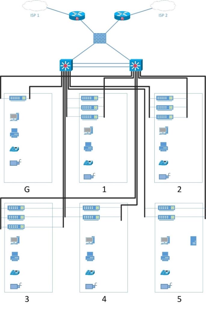
The physical design has the following features:
- The building is equipped with Category 5e cabling and wall plates in the offices, meeting rooms, and so on.
- Within the building, managed switches are used. Managed switches give more control over LAN traffic and offer advanced features to control that traffic. It provides the ability to configure, manage, and monitor LAN and this gives greater control over how data travels over the network and who has access to it.
- The ISP stands for Internet Service Provider. These are companies that provide access to the Internet.
- The firewall is a device designed to permit or deny network transmissions based upon a set of rules and is frequently used to protect networks from unauthorized access while permitting legitimate communications to pass.
2.2.2 LOGICAL TOPOLOGY
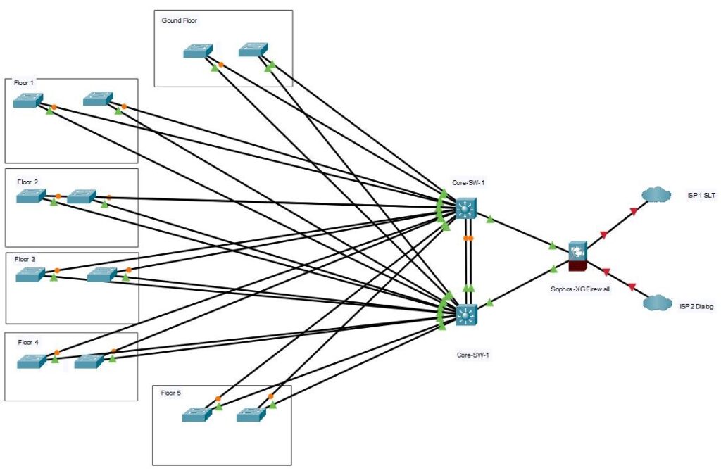
The Logical design describes the following features:
- Company Infrastructure
The Company Network Infrastructure includes three layers:
Collapsed Core layer
A core is called collapsed when you move the role of the core switches to the distribution switches, merging the core- and distribution layer. This Includes high end layer 3 switches and its allows flexibility in network design. Also this layer devices facilitates ease of implementation and troubleshooting the network compared with separate Distribution and Core layer networks and reduces the network design cost from buying additional switches.
Access Layer
The Access layer, located within a company building, aggregates end users from different workgroups and provides uplinks to the Building collapsed core layer. This contains all the devices to allow authorized users in the building to access the network. This includes end-user devices, such as workstations, etc., as well as devices to interconnect the end users to the services they require. This layer is responsible for ensuring that only users who are authorized to access the network are admitted. This layer provides important services, such as broadcast suppression, protocol filtering, network access, IP multicast, and QoS
3. NETWORK DIAGRAMS
3.1 CABLING DIAGRAM
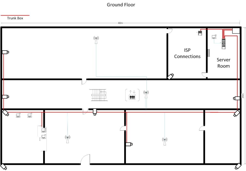
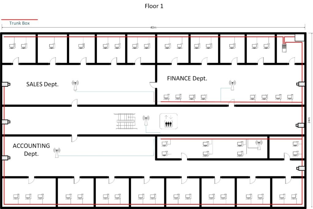
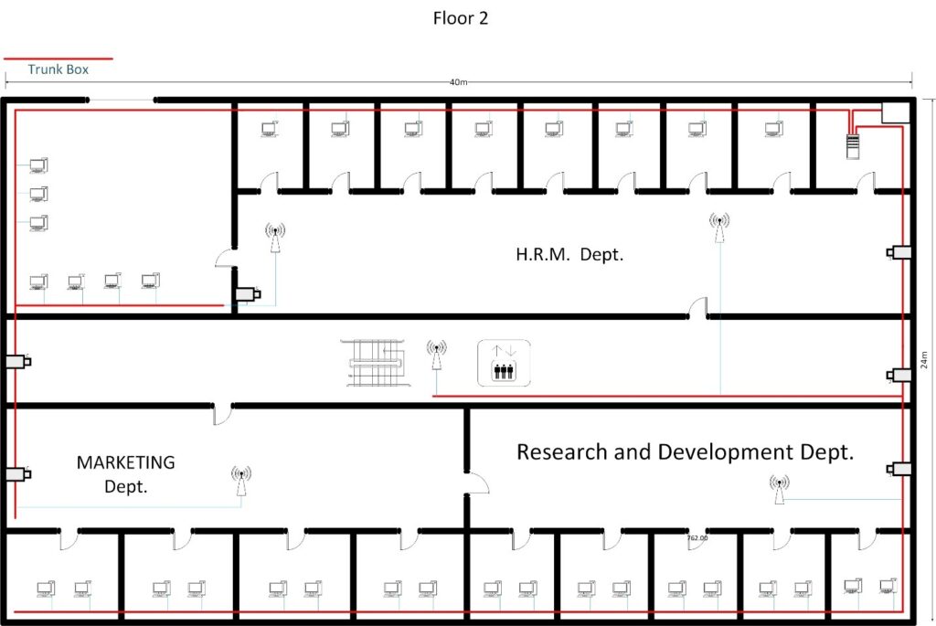
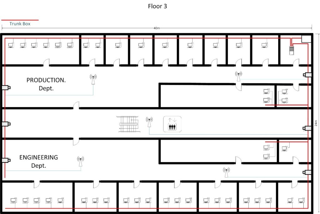
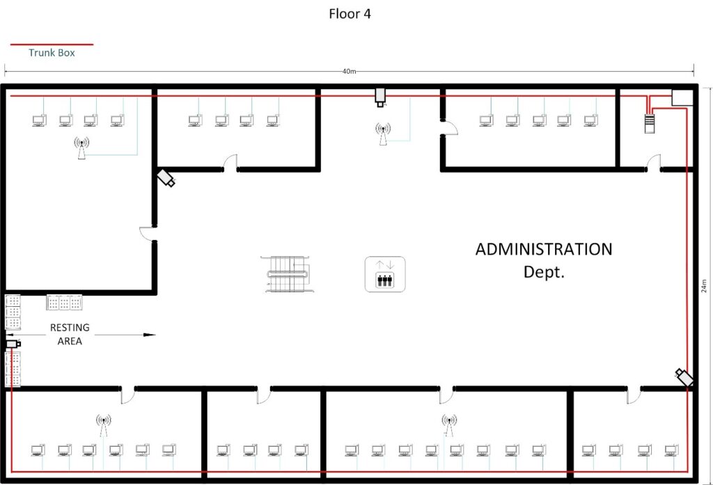
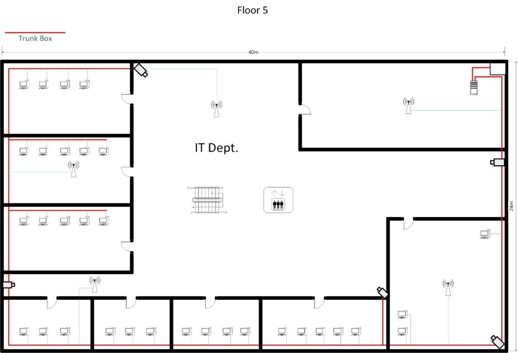
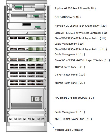
3.2 Server Rack Diagram ( 36U Rack )
4. NETWORK SECURITY
4.1 Firewall Installation
We are planning to implement SOPHOS XG firewall with high performance with high security. Because we need to monitor incoming and outgoing network traffic whether to allow or block specific traffic based on a defined set of security rules. And we are using two separate firewalls because if in case any firewall is down we need to rectify the data traffic from the proper way without any unauthorized access.
We can find out below mention some features (advantages) from firewall:
- Web traffic filtering
- Intrusion Prevention
- Application control (Mobile Apps)
Load balancing
4.2 Antivirus Installation
To protect the end devices from viruses we are proposing to install an Antivirus software for each device are under organization to protect their organization data and polices.
5. PROTOCOLS USED IN THE NETWORK
| Protocol | Description |
| DHCP | Dynamic Host Configuration Protocol (DHCP) is a network protocol that enables a server to automatically assign an IP address to a computer from a defined range of numbers. |
| FTP | The File Transfer Protocol is a standard network protocol used for the transfer of computer files between a client and server on a computer network. FileZilla is a free software, cross-platform FTP application, consisting of FileZilla Client and FileZilla Server. |
| DNS | A DNS server is a type of name server that manages, maintains and processes Internet domain names and their associated records |
| RSTP | Rapid Spanning Tree Protocol (RSTP) is a network protocol that ensures a loop-free topology for Ethernet networks. Nowadays it is a popular solution to implement redundant networks. |
| SNMP | Simple Network Management Protocol is an Internet Standard protocol for collecting and organizing information about managed devices on IP networks. |
| HSRP | Hot Standby Router Protocol is a Cisco proprietary redundancy protocol for establishing a fault-tolerant default gateway. |
| NTP | The Network Time Protocol is a networking protocol for clock synchronization between computer systems over packet-switched, variable-latency data networks. |
| VTP | VLAN Trunking Protocol is a Cisco proprietary protocol that propagates the definition of Virtual Local Area Networks on the whole local area network. |
| PAgP | Port Aggregation Protocol (PAgP) is a Cisco Systems proprietary networking protocol, which is used for the automated, logical aggregation of Ethernet switch ports, known as an EtherChannel |
| CAPWAP | The Control And Provisioning of Wireless Access Points protocol is a standard, interoperable networking protocol that enables a central wireless LAN Access Controller to manage a collection of Wireless Termination Points, more commonly known as wireless access points. |
6. IP ADDRESS & VLAN TABLE
Reserved IP Block: 172.16.0.0/16
Wired Network
| VLAN | Subnet | Description | IPs |
| 100 | 172.16.8.224/28 | Reception & Customer Area | 10 |
| 101 | 172.16.5.0/25 | Administration | 70 |
| 102 | 172.16.6.128/26 | Accounting | 60 |
| 103 | 172.16.8.128/26 | Sales | 35 |
| 104 | 172.16.6.192/26 | Finance | 50 |
| 105 | 172.16.5.128/25 | H.R. | 70 |
| 106 | 172.16.6.0/25 | Marketing | 70 |
| 107 | 172.16.7.0/26 | Research and Development | 50 |
| 108 | 172.16.7.192/26 | Production | 40 |
| 109 | 172.16.8.0/26 | Engineering | 40 |
| 110 | 172.16.7.64/26 | IT (Operations & Maintenance). | 50 |
| 111 | 172.16.8.64/26 | IP Cameras | 37 |
| 112 | 172.16.8.192/27 | IP Printers | 16 |
| 113 | 172.16.4.128/25 | Other Devices (Servers, APs, WLCs) | 80 |
| 114 | 172.16.7.128/26 | Additional Subnet for Device Testing | 50 |
| 658 |
Wireless Network
| VLAN | Subnet | Description | Clients |
| 200 | 172.16.0.0/22 | Employee Network | 670 |
| 201 | 172.16.4.0/25 | Guest Network | 100 |
| 770 |
Total IP Addresses = Wireless Network + Wired Network
= 770 + 658
= 1428
7. ISP CONNECTIONS & BANDWIDTH CALCULATION
7.1 ISP Connections
For this company, We’re going to buy Primary ISP as Sri Lanka Telecom and Secondary as Dialog. In case of primary ISP fails then quickly up the secondary connection without any failure. We are going to implement following fiber lines for the ISP connections.
- 100 Mbps fiber connection (From SLT Connection).
- 100 Mbps fiber connection (From Dialog Connection).
7.2 Bandwidth Calculation
We have assumed the following bandwidth limits for the users categorized.’
• Light users – 512 kbps (Guest Users in waiting area)
• Moderate users – 1 Mbps (Normal Employees)
• Heavy users – 2 Mbps (Company Managers)
| Floor | Department | Wired Users | Usage | Peak Bandwidth |
| Ground | Reception & Customer Area | 10 | 512 kbps | 5 Mbps |
| 1 | Accounting | 60 | 1 Mbps | 60 Mbps |
| Sales | 35 | 1 Mbps | 35 Mbps | |
| Finance | 50 | 1 Mbps | 50 Mbps | |
| 2 | Human Resource | 70 | 1 Mbps | 70 Mbps |
| Marketing | 70 | 1 Mbps | 70 Mbps | |
| Research and Development | 50 | 1 Mbps | 50 Mbps | |
| 3 | Engineering | 40 | 1 Mbps | 40 Mbps |
| Production | 40 | 1 Mbps | 40 Mbps | |
| 4 | Administration | 70 | 2 Mbps | 70 Mbps |
| 5 | IT (Operations &Maintenance). | 50 | 2 Mbps | 50 Mbps |
Total Peak Bandwidth is 540 Mbps. We can assume that all users are not using internet simultaneously at full speed. Therefore, the normal bandwidth is lower that peak value.
Connection Cost per Month
| ISP | Package | Total Monthly Usage | Cost per Month |
| SLT | 100 Mbps Fiber Line | 1700 GB | Rs. 33000.00 |
| Dialog | 100 Mbps Fiber Line | ||
| Total Cost |
IMPLEMENTATION
After all details are finalized and upgrade design strategy complete, the implementation of the network upgrade will transpire with minimal or no downtime within Company. As part of our implementation plan, an initial network test will occur. This will be done during off-hours to minimize possible problems; however, the final test will be done during normal business hours to completely evaluate the network upgrade performance. The following items below will be completely under evaluation:
- Implementing the network with key business and technical goals.
- Validate LAN and WAN technology and device selections.
- Verify the service provider provides the agreed-upon service.
- Identify any bottlenecks or connectivity problems.
- Test the redundancy of the network.
- Analyze the effects on performance during network link failures.
APPENDICES
EXHIBIT A: TEAM CONTRACT
Code of Conduct: As a project team, we will:
- Work proactively, anticipating potential problems and working to prevent them.
- Keep other team members informed of information related to the project.
- Focus on what is best for the project team
Participation: We will:
- Be honest and open during all project activities
- Encourage diversity in team work
- Provide the opportunity for equal participation.
- Be open to new approaches and consider new ideas.
- Let the project manager know well in advance if a team member has to miss a meeting or may have trouble meeting for a given task.
Problem Solving: We Will:
- Encourage everyone to participate problem solving problems.
- Only use constructive criticism and focus on solving problems, not blaming people.
Meeting Guidelines: We Will:
- Plan to have an online meeting once a week before submission of the Part Project.
REFERENCES
- Fitzgerald, J., & Dennis, A. (2009). Business Data Communications and Networking (10th Ed.). Hoboken, NJ: John Wiley& Sons, Inc.
- Oppenheimer, P. (2010). Top-Down Network Design: A systems analysis approach to enterprise network design (3rd Ed.).Indianapolis, IN: Cisco Press.
- Dean, T. (2010). Network+ Guide to Networks (5th Ed.). Boston, MA: Cengage Learning.
- Diane, T. (2008). Authorized Self-Study Guide Designing for Cisco Internetwork Solutions (DESGN) (2nd Ed.).Indianapolis, IN: Cisco Press.
- Teare, D., & Pacquet, C. (2005). Campus Network Design Fundamentals. Indianapolis, IN: Cisco Press.